Introduction to Gear Design
3 What Should They Be Made Of?
3.1 Rating Calculations
Gear-rating calculation procedures have been specifically excluded from this manual. The author feels that there is no simple way to cover this subject without compromising the adequacy of the analysis. Anyone designing gears without access to the appropriate AGMA standards and a willingness to spend some time studying them is asking for a lot of trouble. There are a number of packages available for personal computers that claim to perform “complete gear analysis” according to the current AGMA standards. These are great time savers, but their use by inexperienced designers can be dangerous. There are many factors in the rating formulas that must be carefully considered for each application — factors which even the “experts” may disagree on. The best policy is maintain a skeptical attitude in using any rating method, manual or computerized. Believe in what works, not in computer printouts!
3.2 Gear Materials and Heat Treatment
While material and heat-treatment selection are an important part of any rating calculation, they also have a major impact on the manufacturing processes required. Table 3.1 lists the relative characteristics of some popular gear materials so that comparisons can be made of the manufacturing difficulties of alternate choices. For general applications it is best to confine material selections to those listed in the table. Lots of other materials (including aluminum, powdered metal, stainless steel, and exotic “tool steel” alloys) have been used to make gears, but their allowable stresses and lubrication requirements have not been standardized. If you choose to use a material not listed, you must be prepared to do some digging to get that information and spend the time and money needed to verify its accuracy.
| Relative | Relative | Maximum | Difficulty of | Heat-Treat | ||
| Designation | Cost1 | Durability2 | Strength3 | Hardness | Manufacture | Distortion |
| Through-Hardening Steels | ||||||
| 1018 | 1.00 | 1.00 | 1.00 | 180 bhn | 1.10 | Not a concern with through-hardened steels. (Severe if flame or induction hardened.) |
| 1117 | 1.00 | 1.00 | 1.00 | 180 bhn | 1.10 | |
| 1045 | 1.05 | 1.46 | 1.25 | 270 bhn | 1.00 | |
| 1137 | 1.05 | 1.46 | 1.25 | 270 bhn | 1.00 | |
| 1141 | 1.05 | 1.46 | 1.25 | 270 bhn | 1.00 | |
| 4140 | 1.10 | 2.50 | 1.50 | 335 bhn | 1.20 | |
| 4150 | 1.15 | 2.80 | 1.60 | 360 bhn | 1.30 | |
| 4340 | 1.20 | 3.00 | 1.60 | 390 bhn | 1.40 | |
| 4350 | 1.25 | 3.20 | 1.65 | 400 bhn | 1.50 | |
| Nitriding Steels | ||||||
| 4140 | 1.50 | 3.50 | 1.35 | 48 hrc | 1.25 | Minor |
| 4340 | 1.50 | 3.40 | 1.42 | 48 hrc | 1.25 | Minor |
| Nitralloy | 1.75 | 4.20 | 1.45 | 64 hrc | 1.25 | Minor |
| Carburizing Steels | ||||||
| 4130 | 1.50 | 3.50 | 1.60 | 50 hrc | 2.50 | Severe |
| 4620 | 1.65 | 4.00 | 1.85 | 55 hrc | 2.50 | Severe |
| 8620 | 1.35 | 4.50 | 1.97 | 62 hrc | 2.50 | Severe |
| 4320 | 1.50 | 5.60 | 2.15 | 62 hrc | 2.50 | Severe |
| 4820 | 1.75 | 5.60 | 2.25 | 62 hrc | 2.75 | Severe |
| 9310 | 2.00 | 5.50 | 2.12 | 61 hrc | 3.00 | Severe |
| Iron | ||||||
| G4000 Grey | 0.80 | 0.80 | 0.40 | 200 bhn | 0.85 | Not a concern with iron. |
| Ductile | 1.20 | 81 % of steel | 81 % of steel | 260 bhn | Same as steel. | |
| Malleable | 1.00 | 0.95 | 0.51 | 240 bhn | 1.00 | |
| Bronze | ||||||
| Sand-Cast | 3.00 | 0.10 | 0.17 | 160 bhn | 1.00 | Not a concern. |
| Aluminum Bronze | 5.00 | 0.47 | 0.72 | 220 bhn | 1.10 | |
- Notes:
-
- 1
-
Cost of material and heat treating relative to non-heat-treated 1018 steel.
- 2
-
Durability relative to non-heat-treated 1018 steel.
- 3
-
Strength relative to non-heat-treated 1018 steel.
Through-hardening steels are the most popular gear materials because they can be cut after reaching their final hardness. This eliminates heat-treating distortion that can require expensive finishing operations. The through-hardening steels are listed in order of relative power capacity (lowest to highest), with fully-annealed 1018 steel being used as the “baseline”. Very soft steels are often “gummy” and can be difficult to cut accurately. Cutting steel over 350 bhn can also be a problem.
Steel alloys have different “hardening profiles” (the relationship of hardness to distance from the surface) that must be matched to the size of the part and the hardness needed (see Figure 3.1). Generally speaking, the lower the alloy is on the list, the better the hardening profile. It is important that highly-stressed parts have uniform hardness — soft “cores” can lead to field service problems. The author prefers to limit the use of 1045 material to parts requiring less than 240 bhn. Do not use 1045 for parts that will be operated at low temperatures. 4140 works well for parts up to 3 ndp and for critical sections up to about 400. For coarser pitches and larger critical sections 4340 is preferred rather than 4150. The author does not advocate the use of re-sulphurized steels, as they have an elevated notch sensitivity.
Some alloys, such as 4140 and 4150, can become extremely brittle if hardened over 430 bhn. Always check the “notch sensitivity” of any material that is through-hardened above 375 bhn. Any application for use at extreme temperatures (below 0 °F or above 250 °F) requires careful analysis of the material properties under those conditions. This analysis should be done by a competent metallurgist.
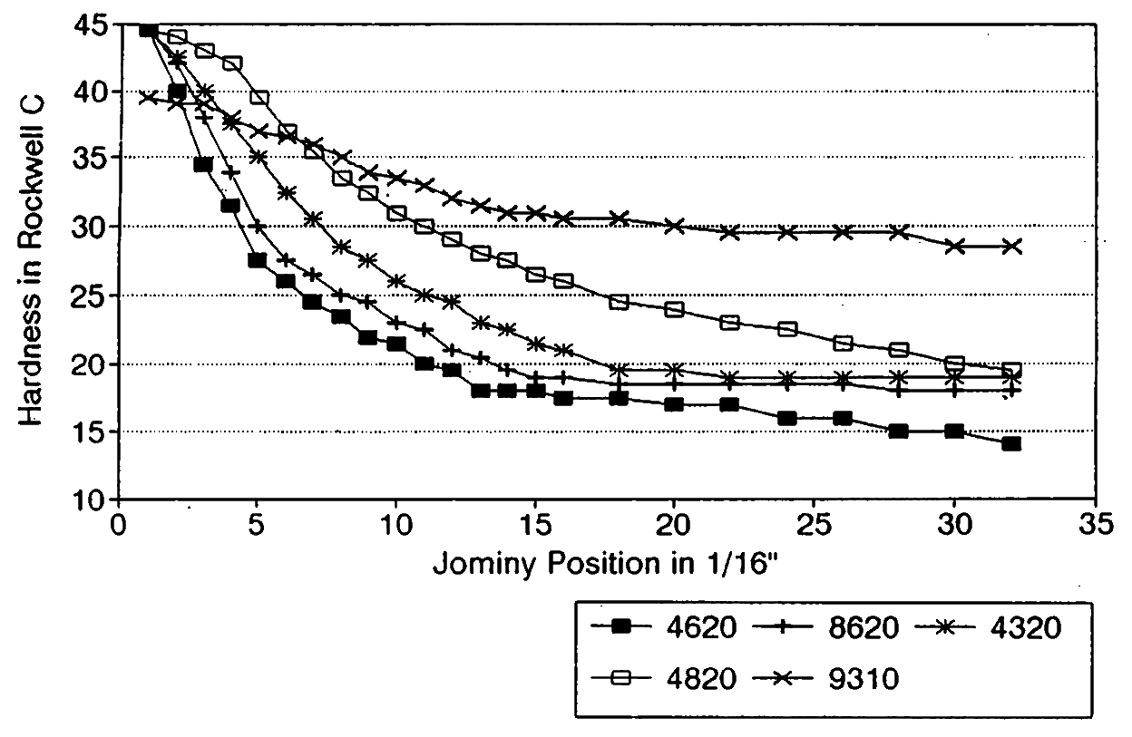
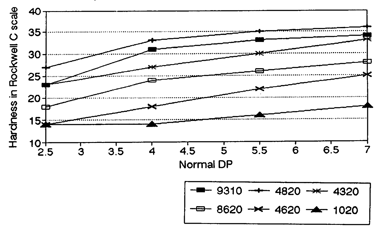
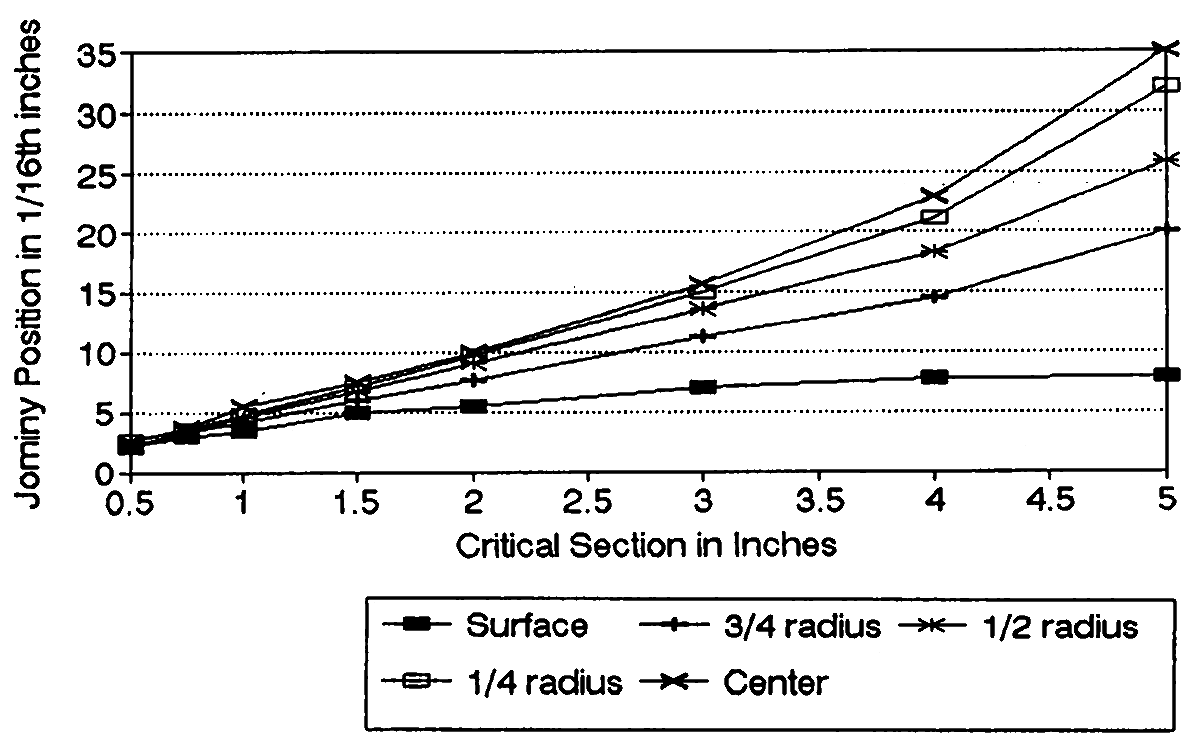
While the AGMA standards do not (at the time this is being written) have different allowable stresses for the various carburizing steel grades, there is ample evidence to suggest that all alloys do not perform equally. Figure 3.2 is a graph of the average (or mid-band) hardness potential of the most popular carburizing steels as found in the “Jominy” hardenability test. There is a significant difference in the curves from one alloy to another. This is important because for carburized gears to perform well the tooth-core hardness must be greater than 25 hrc. Figure 3.3 is a graphical representation of a table in the AGMA 2004 Materials and Heat Treat Manual. It clearly shows, for example, that the popular 8620 alloy will not result in a tooth-core hardness of 25 hrc when the tooth size is larger than 4.5 ndp. Figure 3.4 is a typical graph of jominy position vs. critical-section size.
The actual hardness results will vary depending upon the exact chemistry of the material, the specifics of the heat-treat process, and the critical section (see Figure 3.1) of the part. Alloy selection and critical-section analysis are a very important part of carburized-gear design. The author does not advise using high-performance alloys in all cases, but suggests 8620 not be used for teeth larger than 4.5 ndp or for parts with critical sections over 300. For coarser-pitch application 4320 is preferred.
While nitrided gears can’t carry as much load as carburized and hardened ones, they offer the advantage of minimal heat-treat distortion. This usually allows them to be used “un-ground”, and greatly reduces manufacturing costs. Material selection for nitrided gears is generally made on the basis of the durability rating required. Nitriding produces a very hard, shallow case that can be susceptible to cracking if overloaded. This process is most successful on teeth smaller than 6 dp.
Carburized, hardened, and ground gears are the ultimate in power capacity. Gear grinding is usually required to correct for heat-treat distortion. Attempts at predicting distortion levels and controlling it during the heat-treating process generally have been unsuccessful. Without grinding it is difficult to maintain AGMA Q-10 tolerance levels. Selective hardening is specified to keep some areas of the part “soft”, and this can be done through the use of copper plating or carburizing, machining the case off the desired surfaces, and hardening. Special “stop-off” paints have also been used with great success. Material selections are made on the basis of the durability rating and the case depth required. The AGMA standards and some of the reference books can provide guidance in those areas.
Cast iron is used in many industrial and automotive gear applications because of low material cost. Casting methods have been developed that can produce the required core hardness right from the mold, saving an expensive heat-treat operation. (If not done properly, however, the parts become as hard as tool steel and unusable due to brittleness.) These materials are getting better every year as a result of the research money being spent on them. Some experts feel these new iron formulations can carry the same loads as through-hardened gears of the same core hardness. For high-volume uses the cost savings may make these materials very attractive to those willing to verify the lab results.
Bronze is the material of choice for most wormgears, but is seldom used on other gear types unless the power requirement is low. Some bronze alloys can be heat treated to improve their capacity. Casting methods can greatly affect the material properties, and the gear designer must make sure the drawing specifies the method desired.
Table 3.2: Approximate Minimum Hardenability of 1045, 4140, 4150, & 4340
| Brinell Scale | ||||
|
Jominy Position |
1045 | 4140 | 4150 | 4340 |
|
1 |
555 | 525 | 630 | 525 |
|
2 |
390 | 525 | 630 | 525 |
|
3 |
295 | 514 | 630 | 525 |
|
4 |
270 | 495 | 620 | 525 |
|
5 |
260 | 495 | 615 | 525 |
|
6 |
250 | 480 | 595 | 525 |
|
7 |
250 | 455 | 595 | 525 |
|
8 |
245 | 444 | 575 | 514 |
|
9 |
240 | 410 | 575 | 514 |
|
10 |
235 | 390 | 555 | 514 |
|
11 |
230 | 370 | 540 | 495 |
|
12 |
220 | 360 | 525 | 495 |
|
13 |
355 | 495 | 480 | |
|
14 |
345 | 480 | 465 | |
|
15 |
335 | 455 | 465 | |
|
16 |
330 | 444 | 455 | |
|
18 |
320 | 420 | 444 | |
|
20 |
310 | 400 | 430 | |
|
22 |
310 | 380 | 420 | |
|
24 |
300 | 370 | 410 | |
|
26 |
300 | 360 | 400 | |
|
28 |
295 | 350 | 390 | |
|
30 |
295 | 350 | 380 | |
|
32 |
285 | 350 | 370 | |
3.3 The Gear-Design Process
-
1. Determine Loads and Speeds
-
• Prime-mover nameplate power and speed
-
• Duty cycle
-
• Reliability
-
• Smoothness of operation
-
• External loads
-
• Experience with similar applications
-
-
2. Determine Gear Type
-
• Physical arrangement
-
• Efficiency
-
• Bearing considerations
-
• Noise and vibration
-
• Experience with similar applications
-
-
3. Determine Material and Heat Treatment
-
• Strength vs. wear requirements
-
• Lubrication issues
-
• Space limitations
-
• Process limitations
-
• Cost issues
-
• Delivery issues
-
-
4. Determine Quality Needed
-
• Operating speed
-
• Noise and vibration
-
• Reliability and failure mode issues
-
-
5. Basic Gear Design
-
• Space available
-
• Standardized tooling
-
• Process capabilities
-
-
6. Detail Design
-
• Stress analysis
-
• Raw material form
-
• Assembly issues
-
• Design for manufacturing
-
• Cost review
-


